Overview

Verilog regions are the systematic stages through which the simulator traverses through while executing the relavant code inside it. Before moving onto verilog regions, following are a few concepts which need to be remebered.

Timestep / Simulation Cycle : This is basically the internal clock that a simulator follows. It does not have any time period or any delay. In fact the total number of timesteps or cycles that a simulator executes depends on the timescale and the verilog code that has been written. One important thing to remember is that the delays added in the verilog code determine how many timesteps will be there. Essentially, the number of times a delay is begin executed in the code tells us how many timesteps the simulator will run.

Timescale : This is the term which tell you how much a unit of delay is supposed to treated as in terms of time.

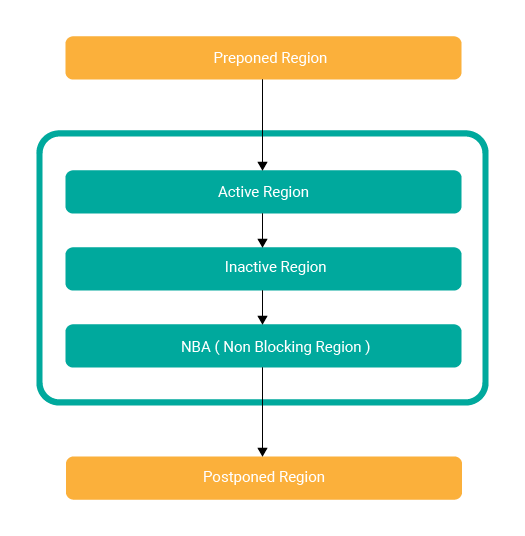
Verilog Regions ( Scheduling Regions )

Given below is an image which can help understand the verilog scheduling regions.

Verilog Scheduling Regions
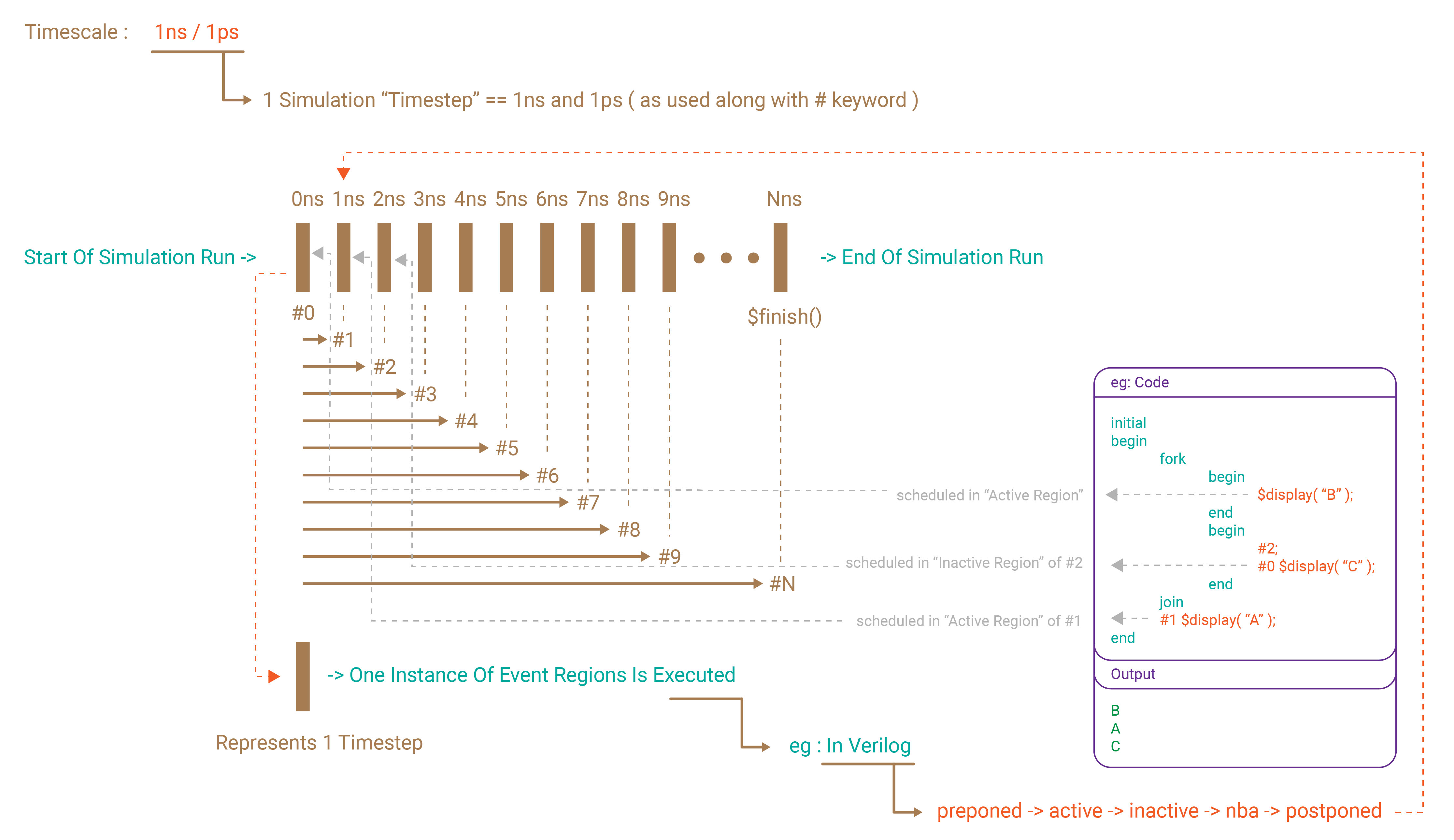
Relationship Between Timestep & Verilog Scheduling Regions

The number of timesteps a simulator will run depends on the simulator and the code itself. In most of the simulators, the number of timesteps is decided by thr number of events happenning in certain time intervals, which is decided by the time scale and the use of # delays. Given below is an image which tries to explain the relation ship between the timesteps and its behavior in accordance with the verilog regions. A small snippet is given in the image to support the explaination.

Verilog Scheduling Regions Pictorial Explaination
Theory Questions
    To introduce a way of mimicing the real world hardware circuits which are parallel in nature of behaviour unlike the digital computing softwares.
    Event Driven simulators are the ones which evaluate the code whenever an event is expected or has actually occured, ie when a varibale chnages values or so. Cycle Driven simulators are the ones which execute the code based ona fixed cycle duration. The most common use for cycle driven simulators is for simulating purely synchronous designs where changes happen only during the clock edges.
    module top;
        initial
        begin
            $display( "A" );
        end
        
        initial
        begin
            #0;
            $display( "B" );
        end
        
        initial
        begin
            #1;
            $display( "C" );
        end
    endmodule
    
    // Output
    
    // A
    // B
    // C
    
    // Explaination : "A" is executed in active region of 0 timestep, "B" is executed in inactive region of 0 timestep and "C" is executed in the active region of 1st timestep
    
    module top;
        initial
        begin
            fork
                begin
                    $display( "A" );
                end
                begin
                    #4;
                    fork
                        #0;
                    join
                    $display( "B" );
                end
                begin
                    fork
                        #3;
                    join
                    #0;
                    $display( "C" );
                end
            join
            #0;
            $display( "D" );
        end
    endmodule
    
    // A -> #0
    // C -> #3
    // B -> #4
    // D -> #4
    
    module top;
        initial
        begin
            fork
                begin
                    #0;
                    $display( "A" );
                end
                begin
                    #0;
                    #0;
                    $display( "B" );
                end
            join 
        end
    endmodule
    
    A -> B ( by using two #0, we are furthur forcing B to be executed after A within in-active region )
    module top;
        initial
        begin
            fork
                begin
                    #1;
                    #0;
                    $display( "A" );
                end
                begin
                    #0;
                    #0;
                    #1
                    $display( "B" );
                end
            join 
        end
    endmodule
    
    B -> A ( A is being forced to execute in the in-active region after #1 )
    Pre-Poned region is where the final sampled values of all variables from the previous time step are finalized and used in the next time step.
    Post-Poned region is in many ways analogous to post-poned region.
    Race condition is where two threads are trying to work with a common variable/signal. For example if DUT is driving a signal, but at that same instance if the TB is sampling the signal, theres a chance that the value may not be sampled correctly by the TB.
    module top;
        reg clk = 0;
    
        always@( clk )
        begin
            clk = ~clk;
        end
    
        initial
        begin
            clk = 1;
        end
    endmodule
    
    During simulation's elaboration, the clk reg value is assigned 0. After which, the always is waiting for a change in clk value. The initial block initiats a change in clk variable's value, which in turn triggers the always. Altough the always is triggered, it never gets re-triggered due to the fact that after the clk value has toggled, the always is executed. Now, in the sencond time around, there is no change in clk and the awlays continues to wait for a change. Hence, the simulation ends eventually with an implicit $finish call.
    No. Only assignment statements can be scheduled to be updated in the NBA region.
Coding Questions
    module top;
    
        initial
        begin
            $displaY("Active");
        end
    
        initial
        begin
            #0; // Schedules everything after this in in-active region
            $display("Inactive");
        end
    
    endmodule
    
    module top;
        initial
        begin
            #0;
            $display( "A" );
        end
        
        initial
        begin
            #0;
            $display( "B" );
        end
    endmodule
    
    module top;
        initial
        begin
            #0;
            $display( "A" );
        end
        
        initial
        begin
            #0;
            #0;
            $display( "B" );
        end
    endmodule
    
    module top;
        initial
        begin
            fork
                $display( "A" );
                $display( "B" );
                $display( "C" );
                $display( "D" );
                $display( "E" );
                $display( "F" );
            join
        end
    endmodule
    
    // There are multiple ways to solve this :)
    
    module top;
        initial
        begin
            fork
                #0 #0 $display( "A" );
                #0 $display( "B" );
                $display( "C" );
                #0 #0 #0 $display( "D" );
                #1 $display( "E" );
                #2 $display( "F" );
            join
        end
    endmodule